
Every unrepaired methane leak represents lost product plus regulatory exposure. That's the backdrop against which EPA Method 21 was written.
This guide breaks down what Method 21 actually requires, how the field procedure works step by step, where it falls short in practice, and how continuous monitoring technology is reshaping leak detection and repair (LDAR) programs across upstream operations.
Key Points
- Method 21 (40 CFR Part 60, Appendix A-7) is EPA's portable-analyzer test for volatile organic compound (VOC) leaks at individual components.
- It classifies leaks — it does not calculate mass emission rates.
- Compliance requires certified instruments, a full component inventory, and a set monitoring schedule.
- Its periodic, manual approach leaves coverage gaps that continuous sensor monitoring now fills.
What Is EPA Method 21?
Method 21 is codified in 40 CFR Part 60, Appendix A-7, titled "Determination of Volatile Organic Compound Leaks." It's the EPA-approved procedure for using a portable, calibrated analyzer to check individual equipment components for VOC leaks.
Here's the distinction that trips up a lot of operators: Method 21 locates and classifies leaks, but it doesn't measure how much gas is actually escaping.
A screening value at or above the applicable leak definition tells you a component has crossed that threshold — it doesn't tell you the pounds-per-hour flowing out of it. That's a separate calculation, and confusing the two can create real problems in an audit.
Method 21 is also the technical engine behind nearly every Leak Detection and Repair (LDAR) program in the oil and gas sector. NSPS and NESHAP rules that mandate LDAR point back to this same procedure.
Equipment and Components Covered
Method 21 Section 1.2 lists the component types subject to monitoring:
- Valves
- Flanges and other connections
- Pumps and compressors
- Pressure relief devices
- Process drains
- Open-ended lines
- Pump and compressor seal-system degassing vents, accumulator vessel vents
- Agitator seals and access door seals
Which of these are actually regulated at a given site depends on the applicable NSPS or NESHAP subpart. Method 21 supplies the how, not the what's covered.
Instrumentation Requirements
The analyzer used for Method 21 monitoring has to meet several specific design criteria:
- Intrinsically safe for use in explosive atmospheres, per the applicable code
- Equipped with an electrically driven pump delivering constant sample flow
- A probe or sampling extension with an outside diameter of no more than 1/4 inch (6.4 mm)
- A meter scale readable to within ±2.5% of the leak definition concentration (this is a readability spec, not a blanket accuracy claim)
Operators can choose from several detector technologies as long as the analyzer meets these specs: flame ionization, photoionization, infrared absorption, and catalytic oxidation detectors are all commonly used in the field.
Why Method 21 Compliance Matters in Oil & Gas Operations
Method 21 monitoring isn't optional paperwork. Many NSPS and NESHAP rules (plus state SIP and FIP programs incorporating them) make it a direct condition of your operating permit. Skip it or execute it poorly, and you're exposed to EPA or state enforcement action.
But the regulatory angle is only part of the picture. Consider what's actually at stake:
- Safety: Fugitive VOCs create fire hazards and tissue-exposure risks for field personnel working near compromised components.
- Lost product: Every leaking connector is saleable gas leaving your revenue stream instead of reaching the sales meter.
- ESG exposure: Investors and regulators increasingly expect data aligned with OGMP 2.0, SASB, and TCFD frameworks, and a sloppy LDAR program undermines that reporting.
Consistent execution protects saleable product, keeps field teams safe, and produces the defensible data regulators and investors will eventually request.
How EPA Method 21 Works — Step by Step
Most Method 21 compliance failures don't come from the test itself failing — they come from incomplete component inventories or skipped calibration checks upstream of the actual measurement. Here's the field sequence technicians follow.
Build and maintain a component inventory. Every regulated component needs a unique ID and documented location, cross-checked against P&IDs. The EPA flags incomplete inventories as one of the most common LDAR failures.
Calibrate the monitoring instrument. Before any survey, the analyzer is calibrated against a reference gas near the applicable leak definition concentration. Zero gas must contain less than 10 ppmv VOC, and calibration runs through the sample probe itself, not around it.
Determine background concentration. Technicians move the probe randomly upwind and downwind, roughly 1 to 2 meters from the component, to establish ambient VOC levels before sampling. This isolates a true leak signal from background noise.
Sample at the component interface. The probe traverses the component's perimeter to find the maximum reading, holding there for roughly twice the instrument's response time. A tighter "within 1 cm" rule applies specifically to rotating shaft-seal interfaces, not every component type.
Compare readings to the leak definition threshold. The maximum observed reading is compared against the leak definition set in the applicable regulation. Method 21 itself sets no universal ppm number; that threshold comes from the specific NSPS or NESHAP subpart governing your facility.
Document, repair, or escalate to Delay of Repair. Under OOOOb, first repair attempts are due within 30 days, with final repair 30 days later. Delay of Repair applies only when repair is technically infeasible without a full shutdown, blowdown, or shut-in, not as a default excuse to push the work back.

Limitations of Method 21 and the Shift Toward Continuous Monitoring
Method 21 captures only a snapshot in time. Surveys typically run quarterly or semi-annual under most permits, meaning a component could develop a significant leak the day after an inspection and run unrepaired for months before anyone catches it.
That gap isn't cheap to manage, either:
- Route-based inspections require trained technicians, calibrated instruments, and travel to often-remote sites.
- Field crews take on real safety exposure just getting to and from wellsites, from weather and road conditions to isolated locations.
- Historical EPA cost modeling assumed roughly 1 minute per valve and 5 minutes per pump seal in labor time for quarterly monitoring, though those figures date to 1980 dollars and don't reflect current labor markets.
Cost isn't the only vulnerability. The EPA's own LDAR guidance flags recurring problems that let leaks slip through even compliant-looking programs:
- Incomplete equipment inventories that miss components entirely
- Improper probe placement during monitoring
- Failure to monitor at the true maximum leak location
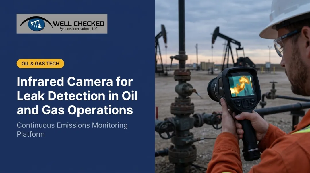
This is exactly why operators are increasingly pairing Method 21 with continuous, sensor-based monitoring, including optical gas imaging, acoustic abnormal-sound detection, and AI-driven anomaly detection, to close the window between scheduled surveys. Well Checked has a USPTO provisional patent filing covering its acoustic anomaly detection technology.
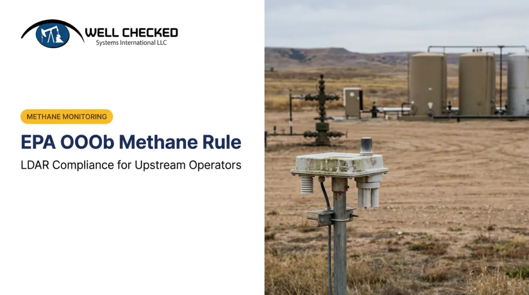
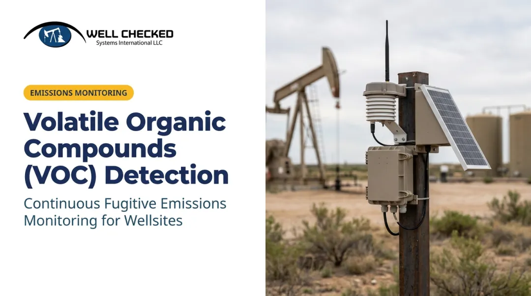
EPA's OOOOb rules already allow approved continuous monitoring technologies to operate in lieu of certain periodic screening requirements, subject to approval and performance conditions. For approved pathways, continuous monitoring is a recognized compliance option under the rule itself, not just a bolt-on workaround.
Well Checked Systems' Zensory.ai™ platform is built around this alternative-monitoring pathway, pairing continuous detection with defensible quantification data.
How Well Checked Systems Can Help
Well Checked Systems built the Zensory.ai™ platform specifically to sit alongside (and, in approved cases, within) LDAR programs like the one Method 21 anchors. It's a multi-sensor system combining Long-Wave Infrared Optical Gas Imaging, acoustic abnormal-sound detection, and video, watching wellsites continuously instead of once a quarter.
A three-tier architecture drives how it works:
| Tier | Function |
|---|---|
| Zentinal Ops™ | Delivers visual and acoustic equipment intelligence: high-resolution video, object recognition, acoustic anomaly detection, and actionable alerts. |
| Zentinal Core™ | Runs multi-sensor detection, learning each site's normal operational baseline in roughly two days, then filtering out routine process signals so operators only get alerted to genuine fugitive anomalies — not noise; supports OGMP 2.0 Level 3. |
| Zentinal IQ™ | Activates only after Core validates an event, quantifying volume, duration, and rate for reporting aligned with EPA's methane rule (40 CFR Part 60 Subpart OOOOb), OGMP 2.0 Level 4/5, SASB, and TCFD frameworks. |
That structure feeds a practical 24-hour acknowledge-dispatch-mitigate workflow: an event gets flagged, the team acknowledges it, dispatches a crew, and mitigates the issue, all inside 24 hours, rather than waiting for the next scheduled survey to even discover the problem existed. Rapid response to a validated methane event can support a documented, timely response outright.
This isn't theoretical. Well Checked currently monitors remote wellsites, including a confirmed continuous monitoring across the Appalachian Basin, processing over 1,500 videos per site per day through onsite edge computing.

Method 21 still does what it's designed to do: give inspectors a rigorous, defensible field procedure. Pairing that with continuous autonomous monitoring closes the gaps between surveys, giving operators both compliance certainty and a faster path from detection to fix.
Frequently Asked Questions
What is Method 21 in LDAR?
Method 21 is the EPA-approved procedure that uses a portable VOC analyzer to detect leaks at individual equipment components. It forms the technical basis for nearly every Leak Detection and Repair program in oil and gas.
What is the LDAR procedure?
LDAR combines a component inventory, scheduled Method 21 monitoring, comparison against leak thresholds, and repair or documentation requirements. Together, these elements control fugitive VOC emissions across a facility.
What equipment is subject to EPA Method 21 monitoring?
Coverage includes valves, flanges, pumps, compressors, pressure relief devices, process drains, open-ended lines, and agitator or access door seals, as defined by the applicable NSPS or NESHAP subpart.
What concentration is considered a "leak" under Method 21?
Method 21 doesn't set a universal number. Leak definition thresholds vary by regulation, subpart, and component type, so check the specific NSPS/NESHAP standard governing your facility for the exact ppmv limit.
How often must Method 21 monitoring be performed?
Frequency depends on your permit and the applicable rule — commonly quarterly or semi-annual. Longer intervals between surveys mean longer windows where an undetected leak can run unrepaired.
Can continuous monitoring technology replace EPA Method 21?
In most jurisdictions, continuous monitoring complements Method 21 rather than replacing it outright. That said, EPA's OOOOb rules do allow approved continuous monitoring technologies, like Well Checked's Zensory.ai platform, to substitute for specified periodic surveys under defined approval conditions.