
Introduction
Undetected gas leaks cost operators far more than the lost product. At wellheads, compressor stations, separator trains, and storage tanks, a single undetected fugitive emission can mean regulatory fines, safety incidents, and ESG reporting gaps that take months to untangle.
Infrared gas detection is the standard continuous monitoring technology across oil and gas production, refining, and chemical processing. Most operators know it detects gas — but not why it works, where it fails, or how to choose between a point sensor, an open-path system, and a modern LWIR camera.
That gap matters. Poor sensor selection leads to missed detections. Poor placement decisions leave entire areas unmonitored. Misread alerts generate alert fatigue that causes teams to ignore the warnings that actually count.
This guide covers the physics behind IR gas detection, how point and open-path detectors differ, how LWIR optical gas imaging cameras extend the technology, and where continuous IR monitoring fits into upstream oil and gas operations today.
Key Takeaways
- IR gas detection identifies concentration by measuring how much infrared light gas molecules absorb — no chemical reaction involved
- A dual-beam design (measurement + reference) cancels out environmental interference from dust, fog, and lens fouling
- Point detectors monitor a fixed location, open-path systems cover beam paths up to 200 meters, and LWIR cameras visualize gas clouds across an entire area in real time
- IR sensors work in oxygen-depleted environments and resist chemical poisoning — two critical advantages over catalytic bead sensors
- Continuous IR monitoring can support EPA methane-rule workflows when an approved method and monitoring plan apply, as well as measurement-based OGMP 2.0 reporting
What Is Infrared Gas Detection?
Infrared gas detection identifies the presence and concentration of specific gases by measuring how much infrared light those gases absorb — without any chemical reaction between the sensor and the gas itself.
IR detection is a purely optical measurement. The gas passes through a light beam, absorbs some of it, and the detector reads the difference. Nothing is consumed. Nothing reacts. This makes IR detection fundamentally different from catalytic bead sensors — and explains why it behaves more reliably under contaminated or oxygen-limited conditions.
What IR Can — and Cannot — Detect
IR detection works on gases with polar molecular bonds that absorb infrared energy at specific wavelengths. This includes:
- Methane, ethane, propane, and other hydrocarbons
- Carbon dioxide and carbon monoxide
- Many volatile organic compounds (VOCs)
It does not work on IR-transparent gases, including hydrogen, oxygen, nitrogen, argon, and chlorine. These molecules either lack the molecular vibration needed to absorb ordinary IR radiation or don't produce the required change in dipole moment.
Operators monitoring for hydrogen specifically must use a separate sensor technology — typically catalytic bead or thermal conductivity.
That limitation aside, IR detection remains the standard for continuous hydrocarbon and CO₂ monitoring in heavy industry — even as electrochemical sensors, photoionization detectors, and laser-based spectrometers have expanded the field. The global NDIR sensor market is projected to reach $1.12 billion by 2031, reflecting sustained industrial demand across safety, process control, and environmental compliance applications.
How Does Infrared Gas Detection Work?
IR gas detection follows a defined sequence: infrared light is generated, passes through a gas sample, is compared against a reference, and the resulting signal is processed to report gas concentration. Each step in that sequence is governed by established physics — which is what makes IR-based sensors reliable enough for continuous industrial use.
The IR Absorption Principle
Certain gas molecules absorb infrared energy at specific, predictable wavelengths. For hydrocarbons like methane, this absorption peak occurs near 3.3 micrometers (µm) — confirmed by peer-reviewed spectroscopy work and NIST reference spectra.
The governing relationship is the Beer-Lambert law: the more gas molecules present in the light path, the more light is absorbed, and the stronger the measured signal. Nitrogen, oxygen, and argon — the primary components of air — don't interfere. These molecules don't produce the changing dipole moment required to absorb IR radiation at the relevant wavelengths. Clean air generates no false signal in a properly calibrated IR detector.
The Measurement and Reference Beam System
An IR source emits radiation through the gas sample. The signal is processed through two optical channels simultaneously:
- Measurement channel — filtered to pass the target gas's absorption wavelength (approximately 3.3–3.4 µm for hydrocarbons)
- Reference channel — filtered to a nearby wavelength where the target gas does not absorb (for example, approximately 3.9–4.0 µm)
The detector compares the two signals continuously. The reference channel is equally affected by dust, condensation, temperature shifts, and lens fouling — but not by the target gas itself. Dividing the measurement signal by the reference signal cancels those environmental variables, producing a stable reading where a single-channel sensor would generate errors or false alarms.

Signal Processing and Alarm Output
A microprocessor calculates the ratio of measurement to reference signal, applies calibration data, and converts the result to a gas concentration reading:
- %LEL (percentage of Lower Explosive Limit) for flammable gas applications
- ppm for lower-concentration regulated gas monitoring
- LEL·m for open-path detectors, where concentration is integrated across the full beam path length
This value is transmitted to control systems, safety panels, or monitoring platforms in real time. Alarm thresholds are set against the site's hazard analysis and regulatory requirements — giving operators a continuous, actionable signal rather than a periodic inspection snapshot.
Types of Infrared Gas Detectors Used in Industry
The three main configurations cover different coverage scales and use cases. They're complementary, not interchangeable.
Point-Type IR Detectors
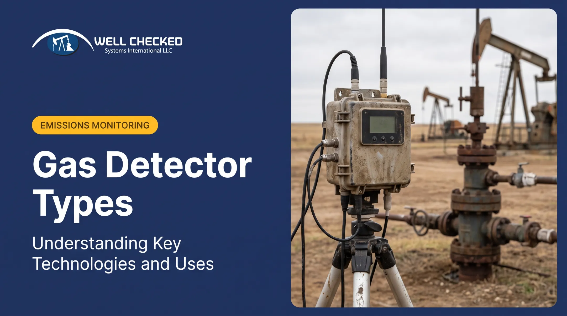
The IR source and detector are housed in a single compact unit. Gas diffuses into a small sample chamber through a sinter or membrane and is measured locally. Results are expressed in %LEL or ppm at that precise location.
Best suited for:
- Fixed high-risk equipment locations (valve flanges, compressor seals, separator vents)
- Enclosed spaces where gas is likely to accumulate
- Applications requiring continuous local concentration data
The limitation is straightforward: point sensors only detect gas that reaches the sensor. A leak on the opposite side of a large process area won't register unless a sensor is positioned nearby.
Open-Path (Line-of-Sight) IR Detectors
A transmitter sends an IR beam across an open space to a remote receiver. Any gas cloud that drifts through the beam path is detected across the entire path length — with results expressed as LEL·m, the product of concentration and distance.
Commercially available open-path detectors are offered in configurations spanning roughly 4–200 m, with many models covering paths up to about 120 m. These are product-specific ranges, not a universal standard — actual range and placement should be validated against dispersion modeling and obstruction assessment for each site.
Open-path detectors are practical for:
- Large open facilities and tank farms
- Offshore deck perimeters
- Facility boundaries where a cloud crossing the perimeter line is the trigger of interest
One installation consideration applies consistently: the beam path must remain clear of obstructions, and transmitter/receiver alignment must be maintained. Partial beam blockage without complete loss can produce misleading readings.

Long-Wave Infrared (LWIR) Optical Gas Imaging Cameras
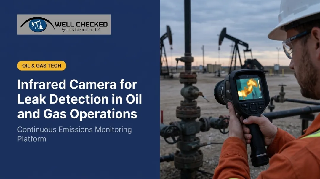
LWIR cameras represent the most operationally distinct form of IR gas detection. Rather than measuring absorption along a single beam, they produce real-time video in which escaping gas clouds become visible as distinct plumes — showing operators precisely where a leak is originating, not just that one exists somewhere in a general area.
Methane optical gas imaging (OGI) cameras use narrower spectral filters matched to specific gas absorption bands:
- Cooled MWIR cameras: typically a 3.2–3.4 µm filter
- Uncooled LWIR cameras: typically a 7–8.5 µm filter range
The general LWIR band spans roughly 8–14 µm, but actual OGI camera performance depends on the specific filter selected, not the broader category.
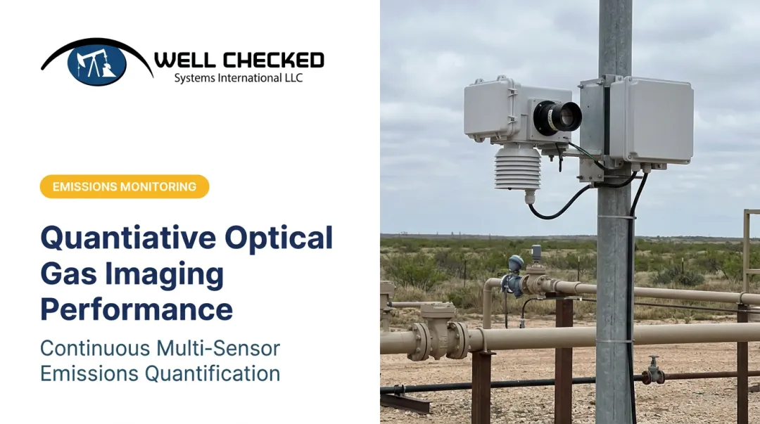
Well Checked's Zensory.ai™ platform integrates LWIR cameras with AI to continuously distinguish normal process patterns from system-validated methane anomalies at upstream wellsites. The LWIR-based approach enables day-and-night detection — a critical capability for 24/7 autonomous monitoring. It also runs at a substantially lower cost than traditional MWIR optical gas imaging systems, making continuous monitoring financially viable for operators managing portfolios of hundreds of remote sites. Well Checked has a USPTO provisional patent filing for Detecting and Quantifying Fugitive Methane and Vapor Emissions Using Infrared Imaging and Machine Learning.
IR Gas Detection vs. Catalytic Bead Sensors
The technology you choose shapes maintenance costs, calibration schedules, and operational reliability. Here's how the two approaches differ in practice.
How Catalytic Sensors Work
Catalytic bead (pellistor) sensors detect combustible gas by measuring the heat released when gas oxidizes on a catalyst-coated bead. This means two things: they require oxygen to function, and they're vulnerable to catalyst poisoning from silicones, sulfur compounds, and lead — all of which are common in upstream oil and gas environments.
IR sensors use no chemical reaction. They require no oxygen for their optical measurement and are immune to catalyst poisoning. Some commercially available IR sensors are rated for service lives exceeding 15 years — a manufacturer-published figure, but one that illustrates the maintenance gap between the two technologies.
Choosing Between IR and Catalytic
| Factor | Favors IR | Favors Catalytic |
|---|---|---|
| Target gas | Hydrocarbons, CO₂, VOCs | Hydrogen (IR cannot detect) |
| Operating environment | Oxygen-depleted, contaminated atmospheres | Standard ambient air environments |
| Catalyst exposure | High silicone/sulfur/lead presence | Clean, non-contaminating atmospheres |
| Calibration frequency | Less frequent (no catalyst degradation) | More frequent (catalyst aging) |
| Upfront cost | Higher | Lower |

Operators monitoring hydrogen-containing streams must use catalytic sensors or an alternative technology — IR cannot detect hydrogen. For hydrocarbon-dominated upstream environments, particularly enclosed vessels, fuel storage, or sites where catalyst poisoning agents are present, IR holds clear operational advantages.
Where Infrared Gas Detection Is Used in Upstream Oil and Gas
Wellheads, separator trains, storage tanks, compressor stations, and flare headers all represent equipment where hydrocarbon fugitive emissions occur. The practical deployment model typically layers all three IR detector types:
- Point-type IR sensors at fixed high-risk locations (valve flanges, pump seals, vent connections)
- Open-path detectors to cover larger pad areas and facility perimeters
- LWIR OGI cameras for continuous area-wide surveillance and source localization
The Regulatory Driver
EPA regulations under 40 CFR Part 60 Subpart OOOOb and voluntary frameworks like OGMP 2.0 are pushing operators toward continuous monitoring as a supplement to periodic leak detection and repair (LDAR) walk-down surveys or, where an EPA-approved alternative method applies, as part of an alternative monitoring plan. OGMP 2.0 membership now spans a substantial share of global oil and gas production, and its Level 4/5 tiers specifically require measurement-based reporting rather than generic emission factors.
Under Subpart OOOOb, continuous IR monitoring is accepted as an alternative compliance pathway only where EPA has approved the specific alternative test method and monitoring plan. Generating continuous data isn't the same as being compliant — the method and its records must satisfy the specific regulatory approval requirements. That distinction shapes how purpose-built platforms approach the detection-to-reporting workflow.
Well Checked's Zensory.ai™ platform addresses this by separating first-line detection from documented emissions quantification:
- Zentinal Core™ runs an AI site-learning cycle (approximately two days per site) to establish a normal operational baseline, then focuses alerts on validated fugitive anomalies rather than every IR signal the sensor captures
- Zentinal IQ™ operates on Core-validated events to quantify emissions volume, duration, and rate via LWIR OGI-based plume analysis, generating compliance logs structured for EPA and OGMP 2.0 Level 4/5 submissions

The platform is deployed across continuous monitoring in the Appalachian Basin.
Other Industrial Applications
IR detection extends well beyond upstream oil and gas. The same sensor principles apply across a range of industries with distinct gas monitoring requirements:
- LNG terminals and petrochemical plants — hydrocarbon leak detection
- Wastewater treatment and biogas facilities — methane and CO₂ monitoring
- Food processing and controlled-environment agriculture — CO₂ monitoring in cold storage and greenhouse environments
- HVAC systems in large enclosed spaces — CO₂ monitoring for air quality and oxygen safety
Performance considerations for outdoor installations: IR detectors perform best when gas composition is relatively stable and the target gas is IR-active. Extreme cold, heavy precipitation, and lens fouling can affect readings. Systems deployed in harsh outdoor environments should include heated optics and reference-beam compensation to maintain accuracy.
Frequently Asked Questions
Can infrared detect gas?
Yes — IR technology detects any gas that absorbs infrared light, including methane, propane, ethane, carbon dioxide, carbon monoxide, and many VOCs. It cannot detect IR-transparent gases such as hydrogen, oxygen, nitrogen, or argon, which require different sensor technologies.
How does an infrared gas detector work?
An IR detector emits infrared light through a gas sample and compares how much light is absorbed at the target gas's specific wavelength against a reference beam at a wavelength the gas doesn't absorb. The ratio between the two signals gives gas concentration.
What is the difference between catalytic and infrared gas detectors?
Catalytic sensors oxidize gas on a heated catalyst, require oxygen to function, and degrade when exposed to silicones, sulfur compounds, or lead. IR sensors use light absorption instead — they work in oxygen-depleted environments and resist catalyst poisoning, which makes them the preferred choice for upstream hydrocarbon monitoring.
What gases cannot be detected by infrared sensors?
IR-transparent gases — including hydrogen, oxygen, nitrogen, argon, and chlorine — cannot be detected by standard IR sensors. These molecules either lack the molecular vibration required to absorb IR radiation or don't produce the necessary change in dipole moment.
What is the difference between open-path and point-type infrared gas detectors?
Point-type detectors measure gas concentration at a single fixed location using a compact sample chamber. Open-path detectors project an IR beam across distances up to 200 meters and detect any gas cloud crossing that beam — reporting results as LEL·m rather than a point concentration. Open-path systems are better suited for wide-area coverage in large facilities where deploying individual point sensors at every location would be impractical.